Memory interfacing in 8085
Contents
- Straight line decoding:
- Straight line decoding:
- Wait Condition Generator:
- Memory Interfacing with 8085/8086 (Address and Data De-multiplexing, Generation of Control Signal)
Straight line decoding:
Straight line decoding:
In small systems, hardware for that decoding logic could be eliminated by utilizing individual high-order address lines to pick memory chips. This is called straight line decoding. Fig. 4.15 shows the addressing of RAM with straight line decoding technique. This method can also be known as partial decoding. It cuts down on the price of decoding circuit, but it features a disadvantage to multiple addresses (shadow addresses).
Fig. 4.15 shows the addressing of RAM with straight line decoding technique. A15 address line, is directly attached to the nick select signal of EPROM after inversion it’s attached to the nick select signal from the RAM. Therefore, once the status of A15 lines are ‘zero’, EPROM will get selected so when the status of A15 lines are ‘one’ RAM will get selected. The status from the other address lines isn’t considered, since individuals address line is not employed for generation of nick select signals.
Wait Condition Generator:
We view that wait states could be introduced within the machine cycles using READY signal to interface slower memory devices. Within this section we will begin to see the circuits for wait condition generator and applying individuals circuits to interface slower recollections.

The Fig. 4.22 shows the circuit for wait condition generator. This circuit generates single wait condition in each and every machine cycle. The circuit operation is offered below.
In T1, the ALE signal is activated, making output Q0 from the first D switch-flop high, presuming RESET (R) is a. Within the next clock pulse i.e. within the next low to high transition of CLKOUT signal from the 8085, the output Q1 from the second D switch-flop goes low. The reduced around the Q1 output initiates 8085 to go in wait condition and resets the very first D switch-flop making its Q0 output low, since Q1 is attached to the ready input of 8085 and also to the reset input from the first D switch-flop. At next low to high transition of CLKOUT, Q from the second D switch-flop goes high making READY pin high and inactivating reset input from the first switch-flop. Fig. 4.23 shows the timing waveforms with this circuit.
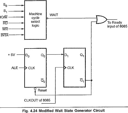
This circuit could be modified introducing wait states for the machine cycle. The modified circuit of wait condition generator is proven in Fig. 4.24. The modified circuit will produce a single WAIT condition for just about any machine cycle that waiting for creation of the device cycle select circuit is logic .

Resourse: https://eeeguide.com/memory-interfacing-in-8085/
